Thursday, April 12, 2012

021 How to model a Drill bit using Catia

In this tutorial, a Drill bit is modeled in Catia using two modules, the generative surface design and the part design modules. The main idea of modeling the cutting blade of the bit was inspired by Abhijeet www.abhijeetks.yolasite.com. This drill bit has two main parts, the spiral cutting blade and the solid part.


This Drill bit is modeled in catia using the following steps:

  1. The cross section of the Drill bit is sketched in either the generative surface design or in the part design modules.
  2. Switching to the generative surface design, four helices are created emerging from the four points of the cross section. Length of the helix should be the desired length of the cutting blade.
  3. A support plane is created at a distance from the first sketch which is also equal to the length of the cutting blade.
  4. The second-end profile of the cutting blade is sketched on the support plane using projection tool.
  5. Switching to the Part design module, the multi-section solid tool is used to generate the Drill bit blade using the two profiles and the four helices.
  6. One surface is created to split the bit tip.
  7. The rest of the bit body is created.
  8. Two sweep surfaces are created down the bit to make the final runway for chips.
All these steps are shown in full details in the following video in order to create a Drill bit..Enjoy!:


Tuesday, March 6, 2012

020 Using Resolve tool to generate parts automatically

In this tutorial,  the Resolve tool under Catalog Editor-Infrastructure module  is used to generate springs that varies in free length and pitch size. the Resolve tool is mainly used to generate parts automatically in CATIA. This tool is used if you want to create catalogs of your own standard parts generated at one directory in your PC.


  • First, the spring is modelled using the Generative shape design module , using the insert menu - wireframe - Helix then, the circular cross section of the spring is defined in the part design module.
  • Second, a design table is modeled using Excel in which three columns are identified ; one for the part number, one for the Height or free-length of the spring and one for the Pitch size, then this design table is saved as a tab-limited text file.


  • Third, the design table parameters (Height & Pitch) are associated with the spring height and pitch.
  • Fourth, using the Infrastructure module - Catalog Editor, under the insert menu, the "Add part family" is chosen, where we choose our spring part.
  • Fifth, we will set the directory where the parts will be generated under Tools - Options - Infrastructure - Catalog editor - Resolved Family Components, then we shall choose where our new parts will be generated.
  • Finally, by right clicking on the family icon under the structure tree, the resolve option is chosen.
Here is the video that shows in full details how to generate spring parts at various height and pitch sizes that could be used in a spring animation video later on.


Sunday, September 25, 2011

019 Aladdin Lamp .. Imagine & Shape

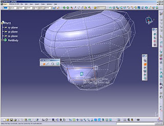
I just finished modeling Aladdin Lamp using "Imagine & Shape" module. I did not make a video tutroial showing how to model it because it was made by trial and error. Nevertheless, in this tutorial, I will show you how to use the tools I used to model this lamp in the imagine and shape module. Here are the images of the lamp:

  
Here are the tools used to model the lamp with a summarized explanation on each tool:

  •  Revolve tool: This tool is used to create the main structure of the lamp. Upon clicking on this tool, you are asked to draw the profile which will be revolved, as shown in the following image. 
  • Revolve Tool

  • Extrusion Tool: This tool is used to create the tail of the lamp. Upon clicking on this tool, you will be prompted to click on the main structure which is the bowl of the lamp, then choose the the face subdivison that will be extruded. you can select the subdivision using edge selection or face selection. I prefer using face selection tool. you can choose more than one face while clicking on the CTRL button. Upon finishing, click on the right button


Extrusion Tool


  • Face Subdivision: This tool is used to create the spout of Aladdin's Lamp. Upon clicking on this tool, you will be prompted to click on the main structure which is the bowl of the lamp, then choose the face subdivision that will be extruded. On the right side of the window, a ratio bar will appear which upon moving, the division of the face will increase or decrease up to your spout diameter. Upon finishing, click on the right button.
Face Subdivision


  • Modification (Space):  This tool is used to shape the spout and the tail of the lamp. This tool is used to modify, translate, rotate and align the structure parts. You can choose either to modify the vertices, the edges or the faces and you can also choose to modify all of them . You may switch the propagation option on, while translating the structure.
Modification Tool


  • Working Zone Definition: This tool is used to shape the spout of the lamp. Upon choosing this tool, you may define the spout parts that you want to manipulate away from the rest of the lamp. This tool gives you the advantage of manipulating some parts of the structure without affecting the rest of the structure. After selecting the working zone, click on the manipluation button to manipulate this working zone.
Working Zone Definition

  •  Erasing: This tool is used to erase the the front face of the spout. upon choosing this tool, you may select the face that will be removed.
Erasing Tool


  • Face Cutting: This tool is used to cut edges with all-round through edges and thus creating more faces all around the bowl. This gives the designer more freedom to manipulate the structure.
Face Cutting