Sunday, September 25, 2011

019 Aladdin Lamp .. Imagine & Shape

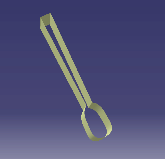
I just finished modeling Aladdin Lamp using "Imagine & Shape" module. I did not make a video tutroial showing how to model it because it was made by trial and error. Nevertheless, in this tutorial, I will show you how to use the tools I used to model this lamp in the imagine and shape module. Here are the images of the lamp:

  
Here are the tools used to model the lamp with a summarized explanation on each tool:

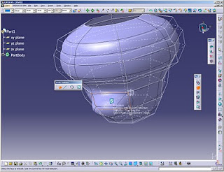
  •  Revolve tool: This tool is used to create the main structure of the lamp. Upon clicking on this tool, you are asked to draw the profile which will be revolved, as shown in the following image. 
  • Revolve Tool

  • Extrusion Tool: This tool is used to create the tail of the lamp. Upon clicking on this tool, you will be prompted to click on the main structure which is the bowl of the lamp, then choose the the face subdivison that will be extruded. you can select the subdivision using edge selection or face selection. I prefer using face selection tool. you can choose more than one face while clicking on the CTRL button. Upon finishing, click on the right button


Extrusion Tool


  • Face Subdivision: This tool is used to create the spout of Aladdin's Lamp. Upon clicking on this tool, you will be prompted to click on the main structure which is the bowl of the lamp, then choose the face subdivision that will be extruded. On the right side of the window, a ratio bar will appear which upon moving, the division of the face will increase or decrease up to your spout diameter. Upon finishing, click on the right button.
Face Subdivision


  • Modification (Space):  This tool is used to shape the spout and the tail of the lamp. This tool is used to modify, translate, rotate and align the structure parts. You can choose either to modify the vertices, the edges or the faces and you can also choose to modify all of them . You may switch the propagation option on, while translating the structure.
Modification Tool


  • Working Zone Definition: This tool is used to shape the spout of the lamp. Upon choosing this tool, you may define the spout parts that you want to manipulate away from the rest of the lamp. This tool gives you the advantage of manipulating some parts of the structure without affecting the rest of the structure. After selecting the working zone, click on the manipluation button to manipulate this working zone.
Working Zone Definition

  •  Erasing: This tool is used to erase the the front face of the spout. upon choosing this tool, you may select the face that will be removed.
Erasing Tool


  • Face Cutting: This tool is used to cut edges with all-round through edges and thus creating more faces all around the bowl. This gives the designer more freedom to manipulate the structure.
Face Cutting


Monday, September 19, 2011

018 Spur Gear Parametric Modeling

In this tutorial, a spur gear is parametrically modeled using Parameters and Relations in Catia. The gear involute is initially modeled using the generative surface design. This tutorial is entirely based on a web page http://gtrebaol.free.fr/doc/catia/spur_gear.html . All what I added here were the videos showing in detail how to model the gear.
The gear is modeled using the following steps:
  • The parameters are defined which are:
    • z : no. of Teeth
    • m: modulus
    • a : pressure angle
    • rp: pitch circle radius
    • ra: addendum radius
    • rb: base circle radius
    • rf: root circle radius
    • rc: corner radius
  • The relations are defined which are the parametric equations for the tooth involute:
    • Yd
    • Zd
  • The points for drawing the tooth involute are defined and a spline is drawn following these points. rotation angle is applied for the ease of modeling.
  • The addendum circle and the root circle are drawn.
  • The root corner is created.
  • Using the split tool, the extra parts of the circles are removed.
  • Using the join tool, the tooth parts are joined together.
  • Using the circular pattern, the tooth is repeated in a full crown, where the angle of repetition is 180 deg devided by the no. of teeth.
  • Shifting to the part module, extrusion is done.
  • Again, this tutorial is entirely based on this webpage http://gtrebaol.free.fr/doc/catia/spur_gear.html
  • At the end, some manipulation is done to test the effect of changing the parameters on the shape of the whole gear.

Here are the two videos showing the modeling of the gear:


Monday, September 12, 2011

017 Cube Modeling using Parameters


In this tutorial, a Cube is modeled using parameters where all the edges of the cube are linked with only one parameter "L". Upon changing this parameter all the cube edges are changed accordingly. The only module used in this tutorial is "Part Design".

This tutorial is quite simple. The Parameter is defined and given the required length which is - in our case - 10mm. Then the sketch of the square is made up where the length of the two sides is linked through a formula to the "L" parameter. Using the Pad tool, the extrusion length is defined the same way. At the end of the tutorial, some manipulations were done on the cube to try different lengths of the edge.

Here is the video that shows the modeling of the Cube:


Saturday, September 10, 2011

016 Adding 3D text "impression"

In this tutorial, 3d text is created using the drawing module and saved as DXF file. This text is then added to another part - in the part design module - as if impressed on it using the pad tool.

Creating and adding 3d text in catia is so simple and is done through following these steps:
  • First, the text is written in the drawing module. After writing the text, you may right click on it, click on properties and change the text type, size, color, weight... etc. according to your desire. then the file is saved as dxf file.
  • Second, open the dxf file and copy the text through selecting the text and right clicking on it. Open the part which you want to add the text to. choose the sketch tool and choose the surface where you want to add the text. and then paste the text and use the transformation tools to adjust the size and orientation of the text.

  • Third, using the pad tool the text will be extruded out of the part. the pocket tool could also be used to engrave the text inside the part instead.
Here is a video that shows how to add 3d text in Catia:


Friday, September 9, 2011

015 Spoon Modeling

In this tutorial, a simple spoon is modeled using generative surface design, free style and part design modules in Catia. The spoon is shown in the following image:

The spoon modeling is done through following these steps:
  • In the generative surface design, the main profile is sketched using the spline tool.


  • Surface is extruded using the surface extrusion tool.

  • Horizontal cutting surface is modeled perpendicular to the first profile and the cutting surface is modeled using the net surface tool in the free style module.

  • The net surface is supported by three spline profiles, the middle of which is modeled a bit deeper in order to obtain a bowl-curvature in the spoon.


  • The spoon surface is extruded using the pad tool in the part design module and the spoon edges are filleted using the fillet feature in the part design module.

Further modifications are done according to your design shaping desire.. enjoy !!
The following video shows the modeling of the spoon: