This is a learning community for Catia for both amateurs and professionals through tutorials. Your participations are highly appreciated through asking questions and providing feedback about the tutorials in the comment box.
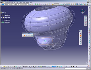
I just finished modeling Aladdin Lamp using "Imagine & Shape" module. I did not make a video tutroial showing how to model it because it was made by trial and error. Nevertheless, in this tutorial, I will show you how to use the tools I used to model this lamp in the imagine and shape module. Here are the images of the lamp:
Here are the tools used to model the lamp with a summarized explanation on each tool:
Revolve tool: This tool is used to create the main structure of the lamp. Upon clicking on this tool, you are asked to draw the profile which will be revolved, as shown in the following image.
Revolve Tool
Extrusion Tool: This tool is used to create the tail of the lamp. Upon clicking on this tool, you will be prompted to click on the main structure which is the bowl of the lamp, then choose the the face subdivison that will be extruded. you can select the subdivision using edge selection or face selection. I prefer using face selection tool. you can choose more than one face while clicking on the CTRL button. Upon finishing, click on the right button
Extrusion Tool
Face Subdivision: This tool is used to create the spout of Aladdin's Lamp. Upon clicking on this tool, you will be prompted to click on the main structure which is the bowl of the lamp, then choose the face subdivision that will be extruded. On the right side of the window, a ratio bar will appear which upon moving, the division of the face will increase or decrease up to your spout diameter. Upon finishing, click on the right button.
Face Subdivision
Modification (Space): This tool is used to shape the spout and the tail of the lamp. This tool is used to modify, translate, rotate and align the structure parts. You can choose either to modify the vertices, the edges or the faces and you can also choose to modify all of them . You may switch the propagation option on, while translating the structure.
Modification Tool
Working Zone Definition: This tool is used to shape the spout of the lamp. Upon choosing this tool, you may define the spout parts that you want to manipulate away from the rest of the lamp. This tool gives you the advantage of manipulating some parts of the structure without affecting the rest of the structure. After selecting the working zone, click on the manipluation button to manipulate this working zone.
Working Zone Definition
Erasing: This tool is used to erase the the front face of the spout. upon choosing this tool, you may select the face that will be removed.
Erasing Tool
Face Cutting: This tool is used to cut edges with all-round through edges and thus creating more faces all around the bowl. This gives the designer more freedom to manipulate the structure.
In this tutorial, a spur gear is parametrically modeled using Parameters and Relations in Catia. The gear involute is initially modeled using the generative surface design. This tutorial is entirely based on a web page http://gtrebaol.free.fr/doc/catia/spur_gear.html . All what I added here were the videos showing in detail how to model the gear.
The gear is modeled using the following steps:
The parameters are defined which are:
z : no. of Teeth
m: modulus
a : pressure angle
rp: pitch circle radius
ra: addendum radius
rb: base circle radius
rf: root circle radius
rc: corner radius
The relations are defined which are the parametric equations for the tooth involute:
Yd
Zd
The points for drawing the tooth involute are defined and a spline is drawn following these points. rotation angle is applied for the ease of modeling.
The addendum circle and the root circle are drawn.
The root corner is created.
Using the split tool, the extra parts of the circles are removed.
Using the join tool, the tooth parts are joined together.
Using the circular pattern, the tooth is repeated in a full crown, where the angle of repetition is 180 deg devided by the no. of teeth.
In this tutorial, a Cube is modeled using parameters where all the edges of the cube are linked with only one parameter "L". Upon changing this parameter all the cube edges are changed accordingly. The only module used in this tutorial is "Part Design".
This tutorial is quite simple. The Parameter is defined and given the required length which is - in our case - 10mm. Then the sketch of the square is made up where the length of the two sides is linked through a formula to the "L" parameter. Using the Pad tool, the extrusion length is defined the same way. At the end of the tutorial, some manipulations were done on the cube to try different lengths of the edge.
Here is the video that shows the modeling of the Cube:
In this tutorial, 3d text is created using the drawing module and saved as DXF file. This text is then added to another part - in the part design module - as if impressed on it using the pad tool.
Creating and adding 3d text in catia is so simple and is done through following these steps:
First, the text is written in the drawing module. After writing the text, you may right click on it, click on properties and change the text type, size, color, weight... etc. according to your desire. then the file is saved as dxf file.
Second, open the dxf file and copy the text through selecting the text and right clicking on it. Open the part which you want to add the text to. choose the sketch tool and choose the surface where you want to add the text. and then paste the text and use the transformation tools to adjust the size and orientation of the text.
Third, using the pad tool the text will be extruded out of the part. the pocket tool could also be used to engrave the text inside the part instead.
Here is a video that shows how to add 3d text in Catia:
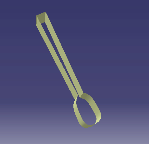
In this tutorial, a simple spoon is modeled using generative surface design, free style and part design modules in Catia. The spoon is shown in the following image:
The spoon modeling is done through following these steps:
In the generative surface design, the main profile is sketched using the spline tool.
Surface is extruded using the surface extrusion tool.
Horizontal cutting surface is modeled perpendicular to the first profile and the cutting surface is modeled using the net surface tool in the free style module.
The net surface is supported by three spline profiles, the middle of which is modeled a bit deeper in order to obtain a bowl-curvature in the spoon.
The spoon surface is extruded using the pad tool in the part design module and the spoon edges are filleted using the fillet feature in the part design module.
Further modifications are done according to your design shaping desire.. enjoy !!
The following video shows the modeling of the spoon:
In this tutorial, a simple fork is modeled using the modules generative surface design and part design in Catia. The fork is shown in the following image:
The fork modeling is done through following these ten steps:
In the generative surface design the side profile is sketched using the spline tool.
Surface is extruded using the surface extrusion tool.
Cutting surface is modeled through another profile perpendicular to the first profile.
The cutting surface is mirrored to the opposite side of the fork.
The two cutting surfaces are used to cut the first extruded surface.
The two cutting surfaces are hidden to continue modeling.
The fork gaps are created through drawing a section that gets extruded then used as a cutting surface to the fork.
The fork surface is extruded using the pad tool in the part design module.
The fork edges are filleted using the fillet feature in the pard design module.
Further modifications are done according to your design shaping desire.. enjoy !!
The following two videos show the modeling of the fork:
In this tutorial, the Cap that had been started in the first tutorial and the second tutorial is finalized using Generative surface design. Finalizing of the cap is about giving it a final color through multiple selections of the cap surfaces and then applying the preferred color.
Here is the video that shows the finalizing operations of the Cap:
In this tutorial, the visor of the cap that was started in the first tutorial is created and the whole cap is finalized. The visor of the cap is also modeled using Generative surface design module in Catia.
The Visor is modeled in ten steps:
The profile of the visor is sketched and the visor surface is extruded using the extrude command.
The Visor surface is split into two pieces using the split tool.
The remainder of the visor surface is again split into two surfaces removing the one in the bowl.
This part is mirrored and the fill surfaces (at the visor side) are joined to create one surface.
The visor is used to cut this one surface removing the part below the visor.
A 3D round corner is applied at the sharp corner of the visor.
A split surface is created through extrusion from the 3D corner and the visor is split once more.
A line is drawn through the visor at the bowl side and a split surface is created to remove the outer part.
Boundary curves are created to define the skeleton structure of the Fill surface operation.
Fill Surface is created and mirrored.
Here is the video that shows in full details how to create the visor:
In this tutorial, a cap is modeled using Generative surface module in Catia. Its design is simple and divided into two parts the bowl and the visor. The bowl is modeled in this tutorial, while the visor is modeled in another tutorial. The bowl is modeled using Generative Surface Design.
The Bowl is modeled in three steps:
A circular surface is created using the fill surface command.
Another Perpendicular surface is created and trimmed to create half circle.
The half circle is rotated several times using the rotate command while keeping the original half circle. This creates the skeleton of the bowl upon which the surfaces will be built using the fill surface command.
Here is the video that shows the modeling of the bowl part of the cap:
In this tutorial, the toggle clamp will be assembled using all the parts that have been created throughout the previous sessions starting by tutorial No. #1 in which the procedure and the concept are described. You shall find all these tutorials in the blog Archive at the left bar of this page.
In The above images shown are the real images of the toggle clamp and the image of the reverse-modeled clamp. Here is the video that shows the simulation of the toggle clamp mechanism:
The assembly was done using the following steps:
The handle support and the handle support mirror part are inserted and assembled using two coincidence constraints and one contact constraint.
The handle and the handle mirror parts are inserted and assembled using two coincidence constraints and one contact constraint.
The L-Plate and the L-Plate mirror part are inserted and assembled using two coincidence constraints with the handle support and the handle itself and one contact with the handle support.
The L-Plate mirror is assembled also using two coincidence constraints with the handle support mirror and the handle mirror part and one contact with the handle support mirror part.
The connection plate is inserted and assembled using two coincidence constraints with the handle support and the handle itself and one contact with the handle support.
Another connection plate (SAME PART) is inserted and assembled using two coincidence constraints with the handle support mirror and the handle mirror part and one contact with the handle support mirror part.
The four pins (SAME PART) are inserted and assembled one by one. They have two constraints for each, Coincidence constraint with the connection plate or the handle and contact constriant with the connection plate or with the L-Plate part.
Here is the video that shows the detailed assembly of the Toggle Clamp:
This tutorial shows how to model the Handle Support or the main clamping part using the part design module. The clamping part has the following dimensions:
To model the Handle Support or the Clamping Part, four steps will be done:
Two Bodies will be created, the first one will be drawn and then extruded.
Then, we insert a body for which we create a profile projected on the surface of the first body.
The profile of the second body is then extruded.
Boolean operation "Intersection" is done to create the final part.
Here are the videos that demonstrate the modeling of the Clamping part:
This tutorial shows the modeling of the Connection Plate which is the second part of the toggle clamp. Its drawing and dimensions are shown in the image below:
To model the the Connection Plate, two steps will be done:
The main cross section including the holes will be drawn.
The whole section will be extruded using the "pad" tool.
Here is the video that demonstrates the modeling of the Connection-Plate:
In this video tutorial, a Toggle Clamp is modeled and assembled using CATIA. It is mainly composed of sheet metal having a thickness of 2 mm. It has a mechanism moving forward and backwards. Actually, this tutorial is a kind of reverse engineering tutorial because I got this Clamp and modeled it. In this tutorial, several Generative sheet metal techniques and Part Modeling techniques are introduced. So I hope this could be of benefit for those who are interested in sheet metal modeling. Shown below are the pictures of the assembled Toggle Clamp.
In the above image, The open-position of the clamp is shown where the grip part is 100% vertical and the handle (the red one) is brought downwards. In this position, the workpiece is let free. By then, the operator can replace the workpiece by another one.
In the above image, The close-position of the clamp is shown where the grip part is 100% horizontal and the handle (the red one) is brought upwards. In this position, the workpiece is fully clamped. By then, the operator can apply whatever production applications he needs to add.
This modeling is long and is, thus, divided into several parts. Today, we will start with part #1 which is the Pin. The rest of the parts shall be found at these links: